APU – AIRBORNE AUXILIARY POWER General description and operation.
The airborne auxiliary power is obtained from a gas turbine auxiliary power unit (APU). The APU is a compact, self-contained unit that provides compressed air for engine starting on the ground. The unit provides compressed air for air conditioning while the airplane is on the ground and at limited altitude in flight. The unit also provides electrical power for use on the ground or in flight.
The APU consists of a gas turbine engine, an ac electrical generator driven by a turbine through an accessory drive, and controls for safe and continuous operation. An engine compressor bleed system is connected to the airplane pneumatic system. Refer to Chapters 36, Pneumatic System.
The generator provides electrical power for the airplane electrical system.
Refer to Chapter 24, AC Generation System. Fire detection, warning and extinguishing systems are also provided for the APU.
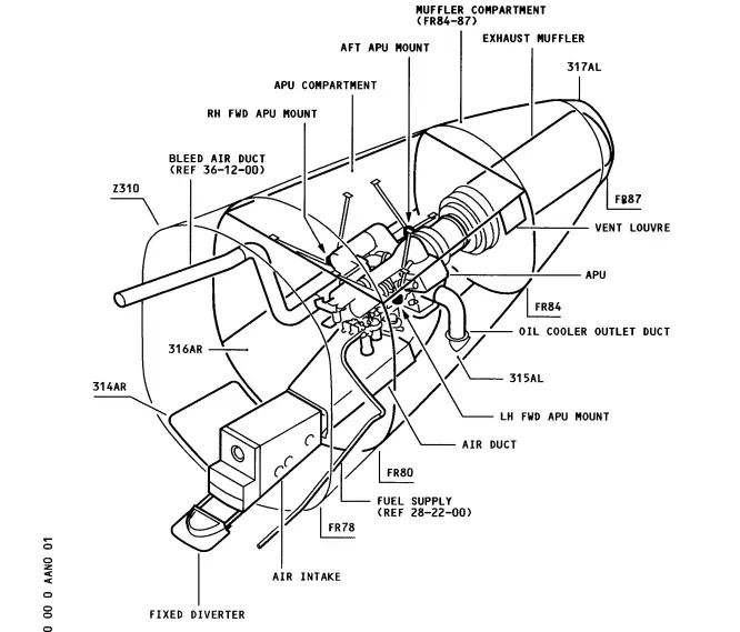
The APU is located in a compartment in the tail section of the aeroplane (Fig. 1). Access to the APU is obtained through a latched access door in the fuselage directly below the APU.
Fuel for the operation of the APU is obtained from fuel tank No. 1 (Fig. 2). Electrical power for starting the APU is obtained from the aeroplane
battery. Positioning the master switch to START initiates automatically controlled operations to start the APU. The APU fuel valve and air inlet door open. Acceleration, ignition, and starter motor cutout are controlled to allow the engine to reach service speed quickly and safely.
As soon as the APU attains the service speed, pneumatic or electrical power is obtained by correctly positioning the controls. If large amounts of pneumatic power are required, such as for aeroplane engine starting, the electrical load must be reduced.
The APU is stopped by positioning the master switch to OFF. The APU shuts down automatically in event of engine overspeed, low oil pressure, high oil temperature, or if there is a fire in the APU compartment. Fire extinguisher discharge, in the event of a fire in the APU, is controlled manually. Refer to Chapter 26, Fire Protection.
A P U Power Plant
The APU power plant consists of the APU engine assembly as installed on
the aeroplane (Fig. 1). The APU engine assembly contains the APU engine, ac electrical generator, and the engine mount brackets.
A P U Shroud
The APU engine and its accessories are enclosed in a fireproof and sound-reducing shroud (Fig. 1). The shroud consists of the upper shroud and the lower shroud.
A P U Mounts
The APU mounts consist of the ring mounts, shroud rings, and engine mounts. The shroud rings provide support for the engine mounts and the upper shroud. The shroud rings are attached to the aeroplane structure with ring mount struts and brackets.
A P U Air Inlet
The APU air inlet provides the compressor inlet air and cooling air to the APU engine. The air inlet consists of the air diffuser duct, compressors air inlet duct, accessory cooling air duct, and the air inlet door (Fig. 1).
A P U Engine
The APU engine is a gas turbine consisting of a two-stage centrifugal compressor directly coupled to a single-stage inward flow turbine (Fig.2). The turbine shaft is geared to the accessory drive section and provides power for driving the engine accessories and the generator.
A P U Fuel System
The APU engine fuel system delivers fuel from the airplane tank No. 1 to the APU engine where it is metered and delivered to the combustion chamber (Fig. 2).
The fuel system regulates the fuel flow to maintain a constant turbine speed under varying load conditions and to maintain turbine temperatures within the safe zone.
A P U Ignition and Starting
The APU ignition and starting system provides the means of cranking the engine and igniting the fuel-air mixture in the combustion chamber (Fig.2). Automatic controls de-energize the starter motor and ignition circuits when the engine is rotating at approximately 35 and 95% (on WA ALL EXCEPT N4569N, N4571M; ON C2-RN3; NH ALL EXCEPT JA8452 thru JA8457;
BU ALL EXCEPT BU LN-SUB, LN-SUK, SN-SUM) and at 50 and 95% (on WA N4569N,
N4571M; ON C2-RN6 and on; NH JA8452 thru JA8457; BU LN-SUB, LN-SUK,
SN-SUM) service speed respectively.
A P U Air
A. The AP U air system consists of pneumatic and mechanical components, which function automatically, to regulate the rate and maximum amount of bleed air that can be drawn from the AP U for use in the airplane pneumatic systems. (See figure 2.)
B. A fan driven by the accessory drive section circulates the cooling air to the ac electrical generator, lubricating oil cooler, and engine accessories. (See figure 2.).
A P U Engine Controls
A. The APU engine controls consist of manually and automatically operated switches to control the starting, stopping and normal running of the A PU engine. The AP U control components are located on the AP U engine, in the A PU control unit, and on the forward overhead panel. (See figures 1 and 2.)
A P U Engine Indicating
The APU engine indicating consists of an exhaust gas temperature indicating system, an elapsed time indicator mounted on the APU for
recording the number of hours the APU has been operated, and an overspeed light on the forward overhead panel. (See figure 1.)
A P U Exhaust
The APU exhaust is a sound reducing system that directs the APU exhaust gases overboard through an air-cooled exhaust duct. (See figure 1.)
A P U Lubrication
The A P U lubrication system is a self contained system that provides pressurized and spray lubrication for all gears and bearings within the unit. It consists of an oil pump, oil tank and various oil lines. (See figure 2.)
A P U Oil Indicating
The A P U oil indicating system provides means of monitoring the high oil temperature, low oil pressure, and low oil quantity with indicating lights, which are located on the forward overhead panel. (See figure 1.)